
Welding is a process to join two pieces of metal by causing fusion between them. The metal pieces to be connected are brought closer and the metal is melted by means of electric arc or oxyacetylene flame along with a filler material added to the joint to form a pool of molten material that cools to form a joint which is usually stronger than the base material.

Types of Welded Connection
1. Butt Weld
2. Fillet Weld
3. Slot Weld and Plug Weld
Butt weld:
In butt welding, two metal pieces are connected which are nearly parallel to each other and don't overlap.
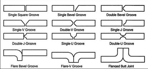
Types of Butt Welds
Source: Autodesk Advance Steel Forum
Specification
- The Size of the Butt weld shall be specified by the effective throat thickness. In case of full penetration butt weld, it shall be taken as the thickness of thinner part joined.
- In case of incomplete penetration, the effective throat thickness shall be taken as the minimum thickness of the weld metal common to the parts joined excluding reinforcement. In case of absence of actual data, it may be taken as 5/8th of the thickness of the thinner material.
- The effective length of butt weld shall be taken as the length of full-size weld.
- The minimum length of butt weld shall be four times the size of the weld.
- If intermittent butt welding is used, it shall have an effective length of not less than four times the weld size and space between the two welds shall not be more than 16 times the thickness of the thinner member joined.
Design Strength of Butt weld
The design strength of the butt weld in tension or compression is given by,
${{f}_{y}}=$ Smaller of yield stress of the weld (${{f}_{yw}}$) and the parent metal (${{f}_{y}}$)
The design strength of the butt weld in shear is given by,
${{f}_{yw1}}=$ Smaller of shear stress of weld $\frac{{{f}_{yw}}}{\sqrt{3}}$ and parent metal $\frac{{{f}_{y}}}{\sqrt{3}}$
${{T}_{dw}}=\frac{{{f}_{y}}{{L}_{w}}{{t}_{e}}}{{{\gamma }_{mw}}}$
${{f}_{y}}=$ Smaller of yield stress of the weld (${{f}_{yw}}$) and the parent metal (${{f}_{y}}$)
${{L}_{w}}=$ Effective length of weld
${{t}_{e}}=$ Effective throat thickness of the weld
${{\gamma }_{mw}}=$ Partial safety factor
$=1.25$ for shop welding
$=1.5$ for site welding
The design strength of the butt weld in shear is given by,${{V}_{dw}}=\frac{{{f}_{yw1}}{{L}_{w}}{{t}_{e}}}{{{\gamma }_{mw}}}$
${{f}_{yw1}}=$ Smaller of shear stress of weld $\frac{{{f}_{yw}}}{\sqrt{3}}$ and parent metal $\frac{{{f}_{y}}}{\sqrt{3}}$
Fillet Weld
In Fillet welding, two metal pieces are connected at an angle. It is also known as Tee joint or corner joint.
Source: Wikipedia
Specification
1. Size of the Fillet Weld
(a) The size of normal fillet weld shall be taken as the minimum weld leg size.
(b) For deep penetration welds with penetration not less than 2.4 mm size of weld is minimum leg size + 2.4 mm
(c) For fillet welds made by semi-automatic or automatic processes with deep penetration more than 2.4 mm, if purchaser and contractor agree.
S = minimum leg size + Actual penetration
2. The minimum size of a fillet weld is specified as 3 mm.
To avoid the risk of cracking in the absence of preheating the minimum size is:
For less than 10 mm thick plate - 3 mm
For 10 to 20 mm thick plate - 5 mm
For 20 to 32 mm thick plate - 6 mm
For 32 to 50 mm thick plate - 8 mm
3. Effective Throat thickness
It shall not be less than 3 mm and shall not generally exceed 0.7t [Kt]* (or t under special circumstances) where t is the thickness of the thinner plate at the elements being welded.
* Value of K for different angles between Fusion Faces
4. Effective Length
It is the length of the weld for which specified size and throat thickness exist.
In drawing only effective length is shown.
Welding length = Effective length + twice the size of the weld
Effective length > 4 times the size of the weld
5. Lap Joint
Minimum lap joint = 4 times the thickness of the thinner plate or 400 mm, whichever is more.
6. Intermittent welds
Length > 4 times the size of the weld or 40 mm whichever is more
Minimum clear spacing = 12 t for compression joints and 16 t for tension joints
Intermittent welds shall not be used in positions subjects to dynamic repetitive and alternating stresses.
${{f}_{wd}}=\frac{{{f}_{wn}}}{{{\gamma}_{mw}}}$
${{P}_{dw}}=$ Design Strength of fillet weld

(a) The size of normal fillet weld shall be taken as the minimum weld leg size.
(b) For deep penetration welds with penetration not less than 2.4 mm size of weld is minimum leg size + 2.4 mm
(c) For fillet welds made by semi-automatic or automatic processes with deep penetration more than 2.4 mm, if purchaser and contractor agree.
S = minimum leg size + Actual penetration
2. The minimum size of a fillet weld is specified as 3 mm.
To avoid the risk of cracking in the absence of preheating the minimum size is:
For less than 10 mm thick plate - 3 mm
For 10 to 20 mm thick plate - 5 mm
For 20 to 32 mm thick plate - 6 mm
For 32 to 50 mm thick plate - 8 mm
3. Effective Throat thickness
It shall not be less than 3 mm and shall not generally exceed 0.7t [Kt]* (or t under special circumstances) where t is the thickness of the thinner plate at the elements being welded.
* Value of K for different angles between Fusion Faces
| Angle between Fusion Faces | 60 - 90 | 91 - 100 | 101 - 106 | 107 - 113 | 114 - 120 |
| Constant, K | 0.70 | 0.65 | 0.60 | 0.55 | 0.55 |
4. Effective Length
It is the length of the weld for which specified size and throat thickness exist.
In drawing only effective length is shown.
Welding length = Effective length + twice the size of the weld
Effective length > 4 times the size of the weld
5. Lap Joint
Minimum lap joint = 4 times the thickness of the thinner plate or 400 mm, whichever is more.
6. Intermittent welds
Length > 4 times the size of the weld or 40 mm whichever is more
Minimum clear spacing = 12 t for compression joints and 16 t for tension joints
Intermittent welds shall not be used in positions subjects to dynamic repetitive and alternating stresses.
Design Strength of Fillet Weld
Design Stress of a fillet weld
${{f}_{wd}}=\frac{{{f}_{wn}}}{{{\gamma}_{mw}}}$
${{P}_{dw}}={{L}_{w}}{{t}_{t}}\frac{{{f}_{u}}}{\sqrt{3}{{\gamma }_{mw}}}$
${{P}_{dw}}=$ Design Strength of fillet weld
${{f}_{wn}}=$ nominal strength of fillet weld $=\sqrt{3}{{\gamma }_{mw}}$
${{L}_{w}}=$ Effective length of the weld
${{t}_{t}}=$ throat thickness $=KS$
$S=$ Size of the weld
${{f}_{u}}=$ smaller of ultimate strength of the weld and the parent material
${{\gamma }_{mw}}=$ Partial factor of Safety
$=1.25$ for shop welding
$=1.5$ for site welding
Slot Weld
A welding technique in which a plate with a circular or elongated hole is kept with another to be joined and then welding is made along the periphery of the hole.
Plug Weld
A welding technique in which a plate with a circular or elongated hole is kept with another to be joined and then the entire hole is filled with filler material.

Source: pursuit engineering


